Process Design
( Company S's Design Change )
Process Design
( Company S's Design Change )
GD.findi has been developed for use in the planning phase as well as in actual production facilities.
In this example, it will be used to facilitate the product design process.
Company Background and Introduction to Production System Simulations
Company S is a highly competitive member in the small compressor technology industry. They have been pursuing technology making their devices smaller and lighter while still maintaining the market needs of high pressure in a small container, and some interest has been voiced in the design of a new product with a higher compression ratio than is currently possible with their existing technology.
Up until this point, S company’s product design cycle consisted of verifying the theoretical capabilities of the product by hand. Since they were not using dynamic simulations to validate the designs, they had been performing mass-production prototyping and gaining feedback though trial and error. This constituted a large expenditure in time, effort, and money for the guarantee of product stability.
This time, however, the introduction of this new product to market had a business requirement of having mass-production being launched at an early stage. It was determined that the front-loading of production verification was crucial to the success of the product in its market vertical.
Therefore, it was deemed essential to perform pre-verification of the production line using a production simulator.
Summary of Setting Changes
Company S’s strength lies within their ability to manufacture an assembly in which the rotor inner wall and vane’s sliding surfaces can move with high accuracy. By leveraging these strengths, they have established a competitive presence in the small-size compressor market. Company S produces a relatively wide range of compressors, but the sliding-vane technology they possess is especially suitable for small-size compressors.
Conventional compressors employ a simple single-stage compression method, however recent advances in compressor technology have given rise to compressors which use a dual-stage compression method and are capable of generating higher pressures.
Production Problems from the Design Change
Of this new product, Company S plans to produce 1400 units annually, roughly 120 units per month. As this product is targeting an expansion of the compressor market in Asia, the changes to be made are at a manufacturing facility located elsewhere in Asia with the goal of producing 120 units per month.
As the design of the product was to change significantly, it was expected that problems pertaining to process design and the floor plan of the production facility would occur. To resolve these problems, new products are first attempted to be manufactured using a virtual production line in the production simulator, and any problems within the process design would appear in advance. By doing so, countermeasures to address these problems could be planned.
Post-Design Change Product Proposal
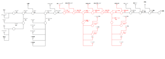
The diagram below highlights the differences in the process design of the old product and the new product. Areas indicated in red highlight areas which have been changed.
Post-Design Change Product Proposal
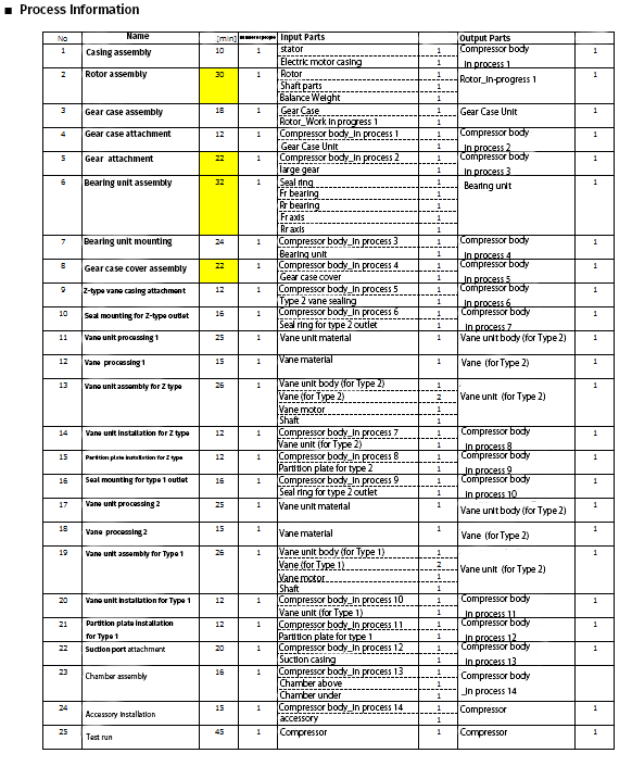
The specifications of the new product are detailed in the table below.
Process Design Proposal Validation – "Production Process Pile"
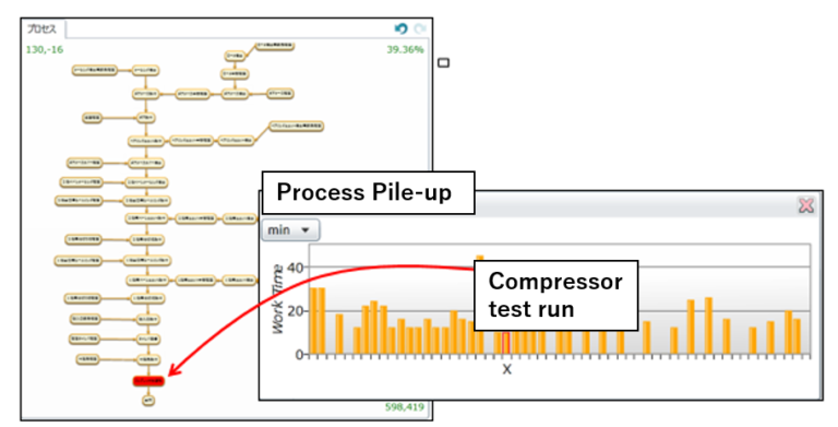
【We set the previous mentioned process information as “production process” in GD.findi and evaluated it in “Production Process Accumulation”. As a result, we found the following.】
-A solution in which a bottleneck is experienced (highest elapsed time) is the baseline “trial run”.
-Upon running this baseline trial run for one day, we see a maximum
output figure of: Uptime / Required time per unit = 480 min / 45 min = 11 units
This performance is acceptable as an output of only 6 units per day is required. As such, a single station as designed fulfills the requirements.
-If a 1:1 step:station ratio is maintained, then an appropriate production volume can be achieved.
Floorplan Draft
The next step is the design of the floorplan of this facility. Firstly, the floorplan of the facility which produced the initial product is shown below.

By changing the original floorplan, a new floorplan will be created with the purpose of producing the new product.
Details concerning the new product are known in advance, so the shortage of stations from the 1:1 step:station ratio is noted. A new floorplan is created as shown in the figure below:
In this case, if the 1:1 step:station rule were to be realized, there would be no place for the machining center. As a workaround for this problem, the two vane-processing stages were made to share the same station.

Floorplan Verification Analysis of Floor stacked column chart
After setting a floorplan within GD.findi, a process was assigned to each station on the trial floorplan.
Upon evaluation of this setup, the following facts were discovered:
-Observing the stockpile of the machining center, it is notable that the cycle time is less than the station preceding it. This indicates that it is idle for some period of time.
–> So the same machining center should be capable of working on two processes without problem.

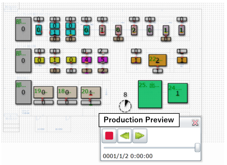
Running the Simulation
Upon independent analysis of the process design and the floor layout of the proposed solution, no glaring flaws are to be seen. The actual feasibility of this plan is then to be validated using a dynamic simulation.
The outcome of the simulation shows 8 units being produced within a single shift. As this exceeds the 6 units/day target required by the business model, the proposed solution is viable and can be put to use.