- Home
- /
- library04_PCB
Simulation of PCB Assembly Line
#Verification of Optimal Input Sequence #Single-Sided and Double-Sided Mounting #Lot-Based Transfer #Equipment Time Chart
Model Overview
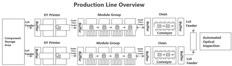
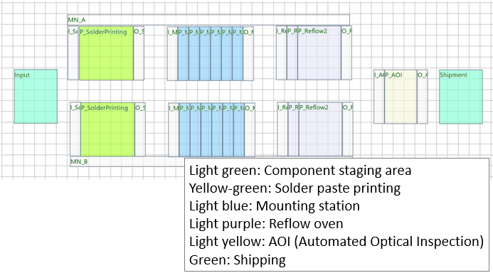
- Production Line Characteristics
- The factory has two PCB assembly lines and one visual inspection machine.
- Input/output between lines is lot-based, while within the line, boards are processed one by one.
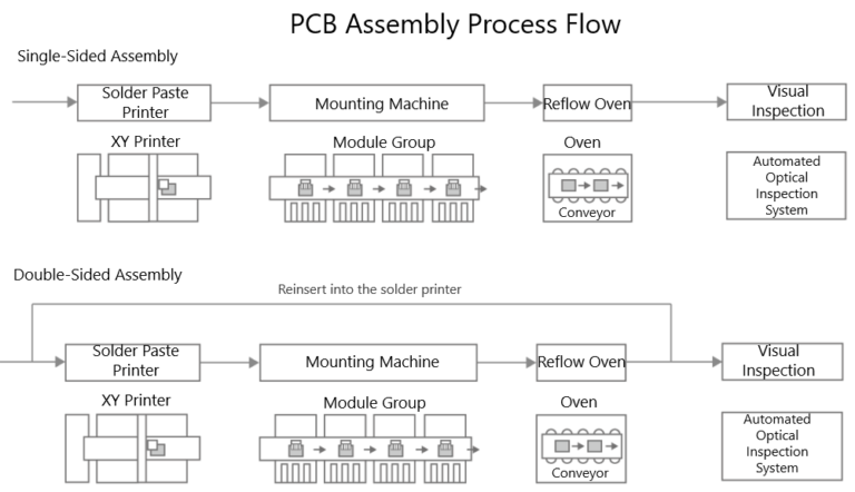
- For double-sided mounting, boards re-enter the same line where single-sided mounting was performed (switching to the other line is prohibited).
- Boards can only be fed into a line when it is empty (after the previous instruction’s reflow process is completed).
- Boards are allocated to whichever line is available to balance production load across both lines.
- Key Points
Understanding and accurately modeling the characteristics of each piece of equipment in the line is essential.
- Mounter Equipment
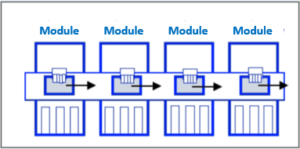
1. Configured as a pipeline of multiple modules.
- Reflow Equipment:
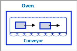
1. Inside the reflow oven, boards move along a conveyor while being heated.
2. Multiple boards can be inside the reflow oven simultaneously.
3. Reflow processing time equals the time taken to pass through the oven.
4. Input interval must be at least 30 seconds.
This simulation model was created to verify the optimal production sequence for maximizing productivity using multiple lines efficiently.
Modeling Screen
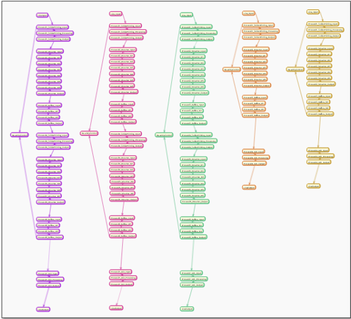
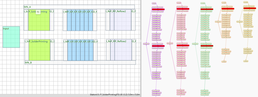
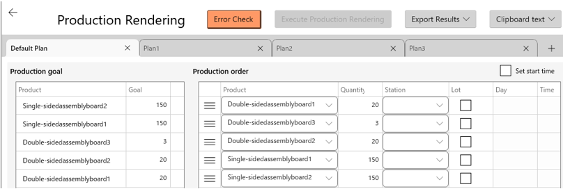

This modeling was created using GD.findi MS.
It is a no-code production simulator that performs production simulations in a digital virtual space, providing powerful support for line design and process design.
Applicable Industries/Line Configurations
- Electronic circuit manufacturing
- Printed circuit board assembly
Output Report Example
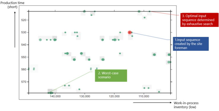
■ Input Sequence Patterns and Throughput
All 120 input sequence patterns were executed and plotted on a scatter diagram.
The scatter plot uses vertical axis = production time (MakeSpan) and horizontal axis = total WIP during production.
Note: The axes are reversed compared to the usual orientation—higher points indicate shorter production time (better efficiency), and farther right indicates less WIP.
Thus, input sequences plotted in the upper-right region represent desirable results.